![]()
The Bridge
By Mark Chirnside
![]()
The Bridge
By Mark Chirnside
Britannic’s bridge equipment was improved compared with that of her sister-ships and many sources describe her equipment levels as being unusually good for a merchant vessel of her type. It is well known that Lusitania, for example, had been constructed to Admiralty specifications and so had special standard controls; but many merchant vessels by comparison did not have such good equipment.
Of particular interest on Britannic is the improvement of the watertight door indicator mechanism, as described shortly after her launching by the technical magazine Engineering:
| 'On the bridge
there will be fitted indicators showing each bulkhead door, and a pointer
in the aperture corresponding to each door, so that the captain can see
not only the position of the door, but the actual closing of the door, the
pointer having a travel of about 6 in. This pointer is actuated by
electrical means, and its position shows at all times the vertical
position of the bottom of the door in the bulkhead.' Engineering, February 27th 1914. |
Her telegraph equipment was ‘most complete’ it was
stated at the time, as the magazine also described:
| 'The three
telegraphs from the bridge to the engine room, made by Messrs. J. W. Ray
and Co., Liverpool, are of their triple-dial all-brass reply and automatic
reply transmitters, the clear glass of each dial measuring 20" in
diameter. Two of these are connected to two 24" engine room indicators;
the third is connected to two extra engine-room indicators through an
entirely different route. The latter three instruments together form an
entirely separate emergency control should the ordinary telegraphs be damaged. All the principle moving portions of the gear have an enclosed type of ball bearing centre, and all the sheaves in the leads are fitted with Ray’s patent phosphor bronze ball bearing pulleys, 6" in diameter, the result being that, although there are no fewer than 312 of these sheaves fitted at the various bends, the friction is so reduced that the levers can be put over from full speed ahead, say, to full speed astern by the easy effort of two fingers on the lever, and the time occupied in moving over the complete range of orders need not be any more than two seconds. The patent automatic direction-indicator, which indicates the first stroke of any change in the direction of the running of engines on the separate third athwart ship dial of all three bridge instruments, does not take even this time, and the officers on the bridge are practically aware of everything done in completing the orders which they have transmitted. For the handling of the ship Messrs. Ray have fitted between the forward bridge and the after docking-bridge four 20" clear double-dial all-brass instruments and one flange-back helm-indicator. Two of these instruments enable any possible order to be given to the engine room to control the engines via the bridge; the others enable a complete set of docking and steering orders to be transmitted and replied to between fore and aft. These instruments are connected by the same 6" ball-bearing pulleys; delta metal chain of heavy description is used instead of the usual copper sash-chain'. Engineering, February 27th 1914. |
According to a contemporary press statement, the
bridge was a ‘completely equipped control centre’ and Britannic’s
officers were in a good position to deal with any emergency threatening their
vessel’s safety,
as they could monitor the rudder, steering response, the main engines’
performance and any Marconi messages. As later dives to the sunken ship have
revealed, in particular one from the 1998 expedition, the main engine indicators
included a small telegraph-like revolution counter, which would have displayed
the revolutions that the reciprocating engines – the largest and most powerful
ever constructed before or since – were making. While operating at seventy-seven
revolutions per minute, the engines each indicated roughly 16,000 shaft
horsepower, producing considerably more when running at their maximum
revolutions; including the turbine engine, at full power Britannic’s
propelling machinery could develop in excess of 60,000 horsepower to drive her
at a maximum speed of some 24 knots. The bridge was described thus:
| 'From there
orders can be given by telephone or telegraph to every working quarter of
the ship, and instruments are provided to demonstrate that most of the
important orders have been carried-out. Thus, there is an indicator to
show the working of the main engines, the operation of the steering
machinery... Pneumatic tubes are provided for the receipt and dispatch of
messages to the Marconi room. The angle of the rudder is
electronically-recorded and the depth of the ocean is sounded by electric
machinery, while the electric submarine bells indicate the proximity of
lightships, etc... Telegraphs also indicate the necessary instructions to the men in charge of anchors and capstans.' Engineering, February 27th 1914. |
By Remco Hillen
As with her interior, the exterior of Britannic’s bridge was also different compared to her sisters -perhaps even more than most people think.Here is a short explanation of how the bridge area on Olympic and Titanic looked like:
Olympic
- The first years of her service she had a rounded wheelhouse, with no rooms between it and the #1 funnel boiler casing. The 2 entrance doors from the outside to the wheelhouse where placed in small alcoves. The Officers Quarters is also shorter when compared to Titanic and Britannic.
- After the massive refit that followed Titanic's sinking things were also changed in this area. Some rooms were created between the #1 boiler casing and the wheelhouse, which was moved forward to compensate the loss of space. The alcoves for the doors were removed. A compass platform was added on top of the bridge. Also, the Officers Quarters were lengthened to the same size as on Titanic and Britannic.
Titanic
- The bridge area was very similar to the one on late-Olympic. But Titanic had 2 rooms between the #1 funnel boiler casing, where Olympic had more. Also, no compass platform was present on the bridge roof.
 |
General lay-out of the bridge area on Titanic
|
©2001 Remco Hillen
Britannic
I’ll explain the situation on Britannic with help from the diagram below.
 |
General lay-out of the bridge area on
Britannic
The 2 long ‘T’ shaped objects that you see are the gantry davits gear channels. Important: The door placement is speculative, I’m still working on that.
|
©2001 Remco Hillen
The amount of rooms between the wheelhouse and the boiler casing is 3 in this deckplan, a cleaned up piece of the Builder’s Plans. When looking at another set of deckplans, the amount of rooms is 2. The portside room has in that case been ‘transformed’ into a corridor. However, I tend to see the Builders' plans as more accurate in this case.
The lay-out wheelhouse is for the most part the same as on Titanic, apart from the small room on the portside.As you can see in this deckplan, the Navigation Bridge has 2 much longer sides as Olympic and Titanic.However, I don’t agree with the deckplan on this.
Photos clearly show that these sides are the same, of small size, as on the sisters, which would be logical.One essential thing on a bridge is that Officers can directly talk/see each other from the wingcabs (the 2 small cabins one can see on both sides of the bridge). There is photo of Titanic which shows Capt. Smith peeking out of the starboard wingcab.I can’t imagine that a bulkhead would be placed directly in this ‘line’ of communication.
 |
The Bridge area on Britannic
Clearly visible is the short bulkhead as on Olympic and Titanic. Also visible is the compass/semaphore platform on top of the bridge roof.
|
The roof on Britannic’s bridge is quite interesting. As you can see in the picture above, there is a platform added on top of the bridge.Late-Olympic also had this, but in a rather different shape and placed more backwards.
The final shape is something one can wonder about too, the Builder’s Model of RMS Britannic shows a different shape, a wider one, than the one present on HMHS Britannic.I see this platform as a ‘stand-in’. I think it would have been replaced by a larger one later.
 |
Looking at the bridge roof from above (without
the platform)
This is the way the Britannic Rigging Plan shows the area. Note in particular the 2 indents of the roof.
|
©2001 Remco Hillen
These set of plans for RMS Britannic indicate 2 indents, with one starboard side stair. HMHS Britannic had the two indents (thanks to Mike Pell for noticing this) but no stair is visible.This confirms again that Britannic wasn’t complete yet and that they were rushing some things to get her ready for service. Thinking further, perhaps they labeled the platform as ‘not too important, although it has to be installed’, and this smaller one with no direct access stair was the solution.
A recent observation (thanks to Michail Michailakis) has uncovered a sort of gate ( #1 in the drawing).It looks to be a simple rope, perhaps it would have been replaced by a real gate when HMHS Britannic would been transformed back into a passenger liner.It would be safe to assume that a gate/rope would have been present on the starboard too.
Finally, to make things a bit easier, here are two diagrams showing how I think the bridge area on Britannic looked from above, for the HMHS and RMS versions.
 |
Topview of HMHS Britannic
Things that are of interest: -The two indents of the roof -The gates/ropes blocking entrance to the bridge -The red lines indicating the platform’s size
|
 |
Topview of RMS Britannic
Things of interest: -The 2 indents of the roof,with a stairway on the starboard side. -The red line indicating the enlarged size of the platform (compared to HMHS Britannic).
|
©2001 Remco Hillen
![]()
Tank Room
By Remco Hillen
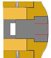
What was changed?
The 2
drawings below show how Britannic’s Tank Room differed from that of her
sister ships.The 2 dark-grey areas were removed, and the lost space was added
forward of the room (light-grey area).Also, a staircase was added inside the new
part forward of the room, this staircase originally was aft of the #3 funnel
deckhouse.


©2001 Remco Hillen
Why was the Tank Room changed?
The dark-grey areas had to be removed to make space for a part of the Gantry davits, the Gear Channel.The staircase had to be moved too,in order to make space for the new Elevator Gear aft of the #3 funnel deckhouse.
![]()
Children's Playroom
By Remco Hillen
 |
Comments by
Remco Hillen:
-The vent placement on this drawing contains some guesses. -The dome cover is also mostly guessed. HMHS Britannic doesn't seem to have the 'boxes' on the sides as Titanic had, but I added them in this drawing.
|
©2001 Remco Hillen
![]()
Gantry davits:How did they work?
By Russell Wild
After the Titanic disaster, shipping companies finally woke up to the fact that their ships simply didn't carry enough life saving equipment to save all onboard. The ensuing rush to add more lifeboats saw the decks of most liners disappear under a mass of davits and associated equipment. For example, the Olympic's once spacious boat deck became fenced in by a wall of boats - not very nice for those wanting to enjoy the formerly uninterrupted sea view. Clearly a new system of boat storage was needed, and Harland & Wolff began to work on just that for their upcoming superliner Britannic.
I
nstead of having an endless row of Welin-type davits as seen on her sister ship the builders opted for a stacked system, with all 48 boats located in one of four groups along the ship. This freed up much of the deck space lost on Olympic, but also necessitated a new type of davit large enough to handle these stacks which could be up to three boats tall. Thus the gantry davit was born.
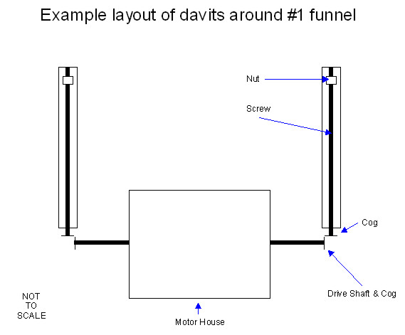
This has been something of a grey area for a while now, because the equipment which operates the davits is largely hidden by the davits themselves (and the boats to a certain extent). However, the clues are there and I have tried to piece them together into the full picture. In doing the research the items which were of most use to me were the builder's plans and photographs of the builders' model. A copy of the "Shipbuilder's" Britannic article was also of some help (thank you to Simon Mills for helping with this). Although you might think the davits look very complicated, you couldn't be further from the truth. They are in fact very simple. Imagine you are using a screw on a piece of wood - what happens when you turn the screw? It moves forwards into the wood. Now imagine, theoretically, that the wood is moving, not the screw. What happens this time? The wood moves along the screw. If you can imagine how that works, you are half way to understanding the operation of the gantry davits! Before we go any further, we need to look at exactly what a pair of gantry davit consists of:
| Two gantry davits | |
| A motor house | |
| Two davit bases on which the davits pivot | |
| Two gear channels with screws | |
| An arm coming from the back of the davits with a nut on the end |
That's all there is to it really. Now we have to see how those things work together.
The gear channels consists of a long screw affixed (probably by some sort of loop hole) to the deck facing outboard, with a cog on the end. On either side is a raised metal cover, most likely to hide the screw which would inevitably be kept well greased and to protect the passengers. The motor houses can be seen quite clearly on photographs of the ship, but what can't be seen is a drive shaft protruding from either side. On the end of the these shafts is a cog which, you guessed it, connects to the cog on the end of the two screws. As the motor turns the two shafts, the cog action turns the two screws we mentioned above. Sounds simple so far?
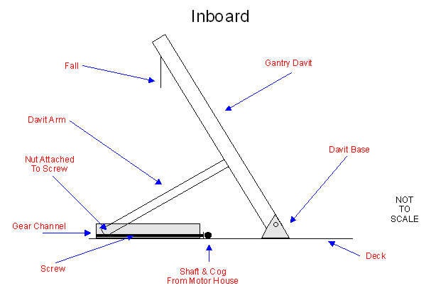
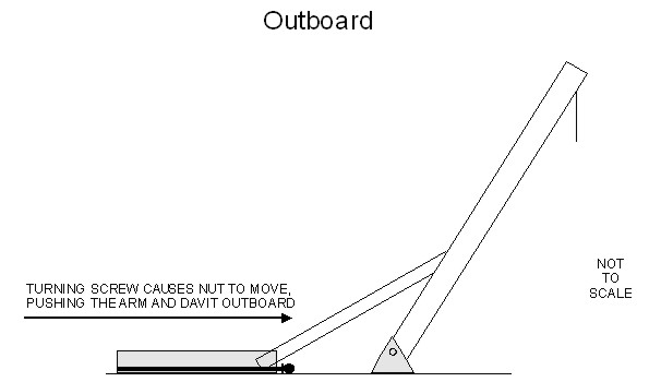
So then, how does this actually move the davits?. That too is quite simple. Earlier we said that each davit has an arm coming from the back. This is true and the arm actually affixes, via a pivot mechanism, to the back of the davit about a quarter of the way up from the bottom. On the other end is a nut which is fixed to the screw on the deck. To summarise then, let's take a look at this system as a whole:
| The motor inside the motor house turns the two shafts protruding from its sides | |
| These shafts have a cog on the end which turns the cogs on the end of the screws (thus turning the screw) | |
| As the screw turns, the nut on the end of the davit arms moves outboard/inboard. | |
| As the arm moves outboard/inboard it pushes/pulls the actual davit which pivots on its base. |
I have included a couple of schematics to help you understand all this better.
|
|
|
||
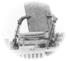
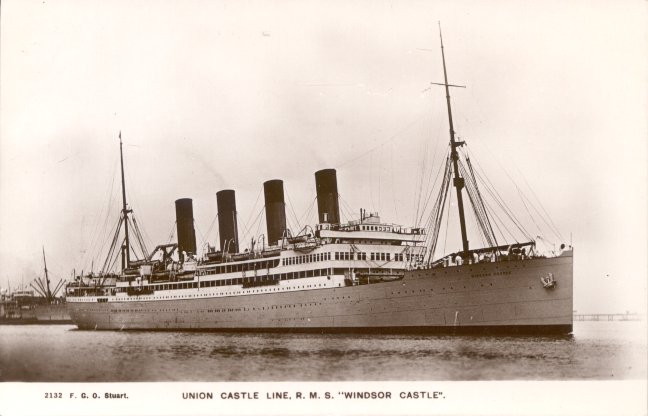
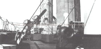
Additional note by Michail Michailakis
The overhead gantry system installed on the Britannic was also installed on the two liners of the Union-Castle Line, the Arundel Castle (1921-1958) and the sister ship Windsor Castle (1922-1943). They were the last liners built with four funnels. They had a single pair of gantry davits (located just after the fourth funnel) plus six pairs of conventional davits. This configuration remained until 1937, when both ships were refitted.
Until now we had almost no information about the performance of the gantry davits installed on the Britannic, apart from the fact that her crew managed to launch many lifeboats in quick succession during her sinking. However, research on the Arundel Castle gave some results. The pair of gantry davits, capable of operating 12 lifeboats, was claimed to be able to launch all of them "in less than 20 minutes". Although this figure is impressive and indirectly confirms the good performances observed on the Britannic, the crew of the Arundel Castle had a quite different opinion. One crew member wrote that "in an emergency they would never have been launched because in practice attempts it took hours to get them out". This comment is quite puzzling if we consider that their White Star colleagues were much faster. Fact is that when the efficiency of the system was tested during a real evacuation (Britannic) the results were very positive. The gantry davits were not installed on other liners. The main reason seems to be their unattractive design and big size during an era of change in ship design.
Source
SS Arundel Castle - Daniel H. Jones (http://smmlonline.com)
![]()
Britannic's Boat Deck
By Remco Hillen
With the sinking of the Titanic, shipping companies were facing a lot of problems. One of the most well known and logical changes was the rule that each ship had to carry enough lifeboats for all onboard. For liners that were already in service, the problems were the biggest. Where do you keep the large number of extra lifeboats on a ship that wasn’t designed to have that amount of boats onboard? The Olympic, after completing 7 voyages with 40 collapsible lifeboats packed on her decks, was send to Belfast for a massive overhaul on 9 October 1912.She wasn’t ready for service until late March 1913. During this overhaul White Star spared no expense to turn Olympic into one of the safest ships in the world. The most notable changes were a new inner skin, watertight bulkheads raised to a safer level and the addition of extra lifeboats (with the new configuration the ship had 64 lifeboats in total). These extra lifeboats were placed along the sides of Olympic’s boat deck. This meant that the boat deck area was hardly usable as a promenade area anymore, since the boats took up quite a lot of space on deck and also blocked the view for the passengers. Although this option had it’s disadvantages, it was the only realistic option Harland & Wolff had.
For ships that were still under construction, things were a bit easier; if one can speak of ‘easier’. The Britannic was still far way from being completed when Titanic sank and Harland & Wolff immediately stopped work on her to see what changes had to be made. In this article I will only get to study her lifeboat configuration.
Seeing the cluttered boat deck of the Olympic, which was definitely far from the original concept of the Olympic class liners, the shipyard designers were challenged to find a solution. They came up with the ‘gantry davits’. These huge girder-like type of davits were able to handle a large amount of lifeboats in a short amount of time and had a lot of other advantages too. However, during the construction and fitting out, Harland & Wolff would be facing another problem; Britannic would be requisitioned as a hospital ship (HMHS). As the still unfinished ship was rushed into action, only five -out of the planned total of eight- sets of gantry davits could be installed. To get enough seats for everyone onboard, there were also installed Welin davits, like on Olympic, mostly along the sides of the boat deck. The boat deck was further packed with stacks of Carley floats and numerous lifebelt lockers. But how would Britannic's boat deck have looked had she been completed for commercial service? Would it have been like Olympic or more like Titanic?
This photo shows the cluttered boat deck of HMHS Britannic.
Harland & Wolff had planned 8 sets of gantry davits, placed forward and aft on the boat deck and 2 sets on the Shade Deck aft on the ship. These sets would be able to carry enough lifeboats for everyone onboard. This meant that all the things that were added to get Britannic ready for hospital service were a temporary solution. With the installation of the davits, over the Officers' Quarters and on the 2nd class and 3rd class promenade areas, the 1st class onboard Britannic had an even less cluttered boat deck in comparison with the same area on Titanic. This can not be said for the 2nd class passengers, who saw quite a bit of deck space taken up by the davits. This was compensated a bit by the extra deck space created above the covered aft well deck (the deck space for the 3rd class passengers is covered in a different article on this website).
There was another interesting thing which happened to the 1st class deck space. The guy wires, the cables which keep the funnels on their place, were laid out differently compared to Britannic's sister ships. Although I can't be 100% sure, I think that this was also done for the benefit of the passengers. The cables on Olympic and Titanic were secured along the sides of the ship. Apparently it was thought they should be laid out in such a way so the passengers wouldn’t have anything to do with them. So, on Britannic the guy wires of the first two funnels were mainly secured along the sides of the deckhouses on the boat deck (e.g. the Gymnasium and the Officers' Quarters). This gives a promenade area which has very little obstructions, like it was on the early Olympic and the Titanic.

This is a picture from my still unfinished RMS Britannic model. The 1st class area can been seen on the right. On the left of the lifeboat station is the 2nd class area. Notice how empty the boat deck looks without the presence of the Wellin davits along its sides.
Although the gantry davits didn’t do Britannic’s profile a lot of good, they were of huge benefit for Britannic and her passengers:
-They gave a less cluttered boat deck than her sister Olympic.
-Lifeboats could be lowered much easier, as the gantry davits were operated by machine power.
-Lifeboats could be lowered even with a severe list.
-The lifeboat stations were spread out better over the ship, 3rd class was now much closer
to lifeboats.
The White Star Line even used the gantry davits as an advertisement. This is a nice indication of how the people in those days thought of the davits; much different from how most people now look at them. It’s heard often: “Those davits make her look a bit unsightly”. But would people in those days, have cared much about how the ship looked? Safety was important, and one cannot deny that the look of the gantry davits would have given people a sense of safety. Along with their practical benefits, they were also a superb choice by the design department of Harland & Wolff.
![]()