|
|
|
Host USB implementation example : I)
Presentation :
The purpose of this article is to introduce a host USB Full Speed implementation. This host is disigned to control MASS storage peripherals like USB key, cameras, hard drive... I advise you before starting reading this article to have a look on the USB tutorial page where I make some essential recalls to understand USB operation : enumeration, mass storage commands... This article is available here. Many people use keys USB to carry datas, and sometimes certain electronics specialists would like to use them to offer convivial and simple human interface to their electronic applications. It is to answer this request that I decided to publish this article. The code that I propose needs some improvements, and I am agree to improve the code with your own improvements. However the code that I give is functional on a majority of USB keys (those which I could test). I give also log file made with a TRACKER110 of the Ellisys company. Even if you do not have a TRACKER110 you can visualize the file log using the downloadable free software on the site of the manufacturer. This USB stack uses less than 9Ko of program memory and less than 540 bytes of ram memory. So this stack can be easily integrated in small embedded systems. II) The hardware Before starting programing USB operation, it is necessary to make a functional board which contains the necessary to work as a USB host ; a microcontroller and a SIE. A SIE (Serial Engine Interface) is the hardware interface between the microcontroller and the USB bus, this interface manages all the hardware functions of the bus : level adapter, NRZI, decoding, bit stuffing, buffer storage. This component is generally called PHY (like physical). Here I decided to use a Cypress component ; the SL811HS. This component is a host/device which can work in FULL SPEED or LOW SPEED. Here we will work only in FULL SPEED; LOW SPEED keys will be rejected. The current keys work in FULL SPEED and most of them in HIGH SPEED. Generally keys called USB2.0 are capable to work in HIGH SPEED, but if the host doesn't support the HIGH SPEED, these keys will work in FULL SPEED (12 Mbits). Even if this host is only capable to work in FULL SPEED the HIGH SPEED memories will work fully with it.  This component is directly
connected to the microcontroller with a 8 bits parallel interface and
some control signals. Its supply must be a 3.3V supply what implies the
use of a voltage regulator that is made using a transistor and a diode
zener(Q3 and D4). Please note that the microcontroller supply is made
in 5V, but there is no problem with regard to connection to the SL811
because the SL811 is "5V tolerant".
There is a serial port on the board to debug with "printf()". The type A USB port receives 2 wires of data (data+ and data-) and 2 wires of supply. The USB supply is permanent what implies that the peripheral will be supplied since its connection, moreover the board doesn't verify overcurrent. Two 15K extra resistances pull down both data lines : The use of these resistances is defined in the USB standard. Here the main part of the schematic: 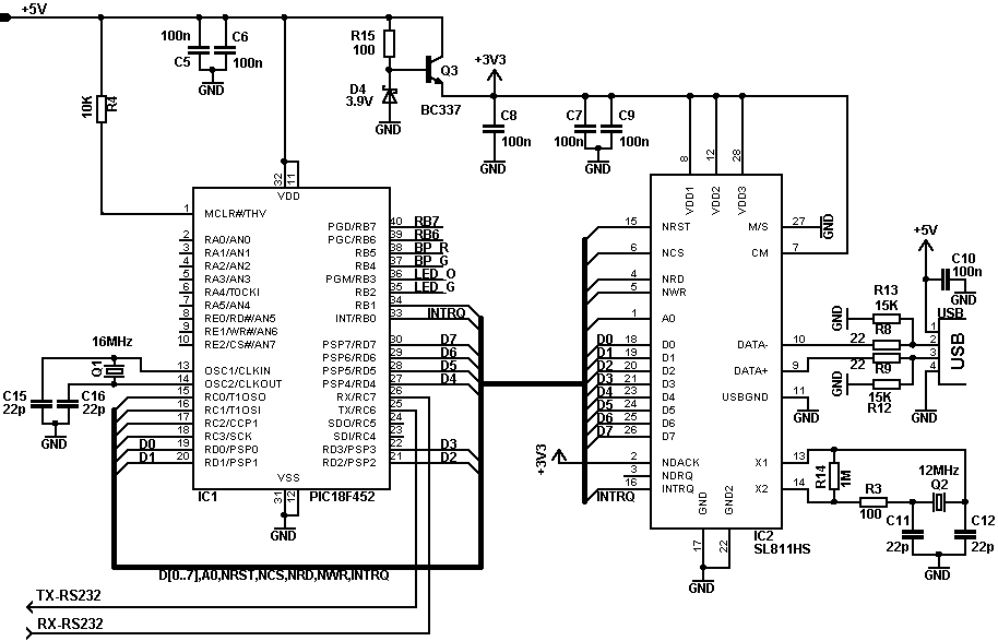 III) Interface functions with the SL811 It is now necessary to consider
the software part of our host. Initially it is necessary to implement
some functions which will make the communication between the SL811 and
the microcontroller. The communication with the SIE is made by using
one 8 bits bidirectional data bus. Five signals are necessary to
control the communications:
Please note that the DMA
communication is not used in this application. Thus it will be
necessary to leave signal NDREQ off-line and to force signal NDACK to
Vcc. You can notice that the interruption pin of the SL811
is connected to RB0, however it will not be used in the program. This
pin should be use in other applications, that is why I decided to
connect it.
The SL811 has many 8 bits registers. The read/write operation are made in two main stages : First the microcontroller writes the register address on the data bus and validates writing by pulling down WR signal, then it makes a read or a write using the RD/WR signals. Warning : Paid attention on the port direction, the microcontroller had to change port direction before reading a data from the SIE. Reading register example: 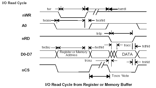 Writing register example :
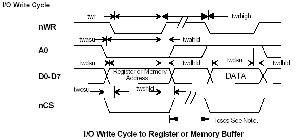 The SL811 is not only capable
of write/read one byte, endeed it can read/write several bytes in burst
mode. The functions sl811_write_buf(..) and sl811_read_buf(..) use
this burst mode.
You can download the datasheet of the SL811 in the heading "Download documentations" at the end of the article. We can consider that the interface microcontroller/SL811 stops here. From now the functions are USB specific functions. IV) USB host functions The purpose of this paragraph is to introduce enumeration functions (enumeration cf. USB tutorial here). As we saw in the tutorial the first operation to do is to detect the speed of the peripheral. To make this opreration the host checks a high level on data+ for Full Speed peripheral and high level on data- on Low Speed peripherals. This host can't drive Low speed peripheral in order to simplify its implementation. If the host detects a peripheral LOW SPEED connection the program break in failure. So on the other hand, if the peripheral is a FULL SPEED peripheral (or HIGH SPEED), the host begin to maque a USB_RESET after temporization 100ms (100ms to wait the stabilization of the supply). This command pull down both lines data+ and data- during 10ms, the peripheral knows that it must be initialized (reset usb defines in the standard). First USB request had to be a SET_ADDRESS, this request change actual address (after reset address is 0x00). If we have a look at this function we see that this request starts by sending a SETUP packet followed by 8 bytes data corresponding to request SET_ADDRESS. Then the function sending a IN packet which the peripheral answers a empty DATA packet to check if the command successfull passed. The second request which we find is the request that checks the peripheral classe : MASS_STORAGE. This request is GET_CONFIGURATION. Please notice that this request was written to read several descriptors at the same time, it reads 32 bytes here. It reads in fact 4 descriptors : the first is the CONFIGURATION descriptor, the second is the INTERFACE descriptor and the two last are ENDPOINT descriptors . I located the interesting fields by boldfacing them. The bytes which are read are organized as follows:
The host is going to control the class of the peripheral, here its checks if it is a MASS_STORAGE peripheral. The field where the classe type is specified is the 14st byte ; this byte is set to 0x08 if it isMASS STORAGE classe. Then the host then will read the ENPOINT numbers which it must use to send and receive the data to/from the mass storage peripheral. V) MASS_STORAGE functions The enumeration is now finish,
it is time to implement MASS_STORAGE functions. There are many
functions MASS_STORAGE in the standard "Bulk Only", here I will be
satisfied with the minimal functions to the control the peripheral :
The functions are SCSI functions sended in USB packets. All functions are sent with the same principle : the first stage is to send command in a CBW packet, the second stage is to recieved or transmit data, and the last stage is to recieve a CSW packet to check the status command (see tutorial). If you need to have more precisly information I advice you to have a look at the "Bulck Only" standard, this standard is available on the end of this article. VI) Practical realization All necessary files are
available to free download :
The board is a simple side board which is easier to be produced by non
professional people. The are some advice to make your own PCB here.
Component list
:
Component provision: 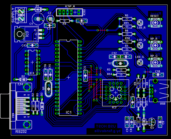 First version of the board (the pcb slightly changed on the new version) 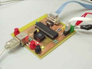 Development:
I advise you to use DIL support for the PIC. The first test is to verify the power supplies. Use a 9 - 12V power supply and plug it in the supply connector of the board. If your board has no problem you have to measure 5V on the output of the voltage regulator and 3.3V on the transitor emitter (Q3). If these tests are succesfull you can insert the PIC and the SL811 in their respective support. I decided to provide the source codes of the firmware in full version. It will be diffused under licence GPL. The program is delivered without guarantee. I encourage you to improve it and to send me your own improvements. Perhaps some USB keys do not work with this code : indeed, in spite of the USB and Mass Storage standards, we always finds manufacturing who move away more or less from these standards. I hope that with this article I would have given interest to start in the USB worl. The software reads sector 0, increments byte 508, and writes the modified sector. If I chose byte 508 of the sector it is in fact not to deteriorate the sector 0 which is a necessary sector for the File System (FAT or other). This board doen't drive File Sytem it is only capable to write sector per sector the memory oh the mass storage device. To get the source files and hex files please click on icon mentioned below and fill the form : If you make modifications in this code thank you to communicate them so that I can redistribute new versions. My goal by distributing this free source code is to help the non professional people to start with USB, moreover I would like the code doesn't stay static and I incite each people to propose his improvements and makes its some profit the community. It is the principle of the free software. I hope that you will play the game... VIII) Run the USB host As you saw in the hardware paragraph the board has a serial port which will allow to send inforamtions to follow the software operation. Use the serial port is not necessary but it provide a good way to develop and to understand operation. To begin I advice you to program the microcontroller with the HEX file, so you will check the good (or bad maybe...) operation of the host. To display serail information from the board the best way is to use a software like Hyper Terminal. You have to configure the communication : 1 start bit, 8 data bits, and 1 stop bit, speed 115200 bits/s. For that use a final software series (ex hyper final under Windows) and connect your chart on the port series of the computer. It will be necessary to regulate the configuration of the port: 1 bit of start, 8 bits of data, 1 bits of stop, speed 115200 bits/s. An animation is avialable undermentionned, click on the picture to start animation.  The green led is powered ON
as soon as the program starts. The orange led powers ON when the key is
connected, it powers OFF as
soon as the writing is finished.
This USB stack uses less than 9Ko of program memory and less than 540 bytes of ram memory. So this stack can be easily integrated in small embedded systems, with small uC like PIC. This stack in only a simple USB stack which drive also UFI communication, but it isn't able to manage files systems (FAT for example) : you can find lots of useful informations about FAT implementation at this link http://www.oryxmp3.com. Contrary to USB stack implementation we can find lots of informations and free examples about FAT files systems. IV) Dowload files You can download the recording file of the host operation. This file must be open with VisualUSB that is free downloadable on Ellisys web site. You can Vous pouvez télécharger le fichier log de l'exemple précédent. Vous pouvez ouvrir ce fichier avec le logiciel gratuit téléchargeable sur le site d'Ellisys. USB standard is downloadable in www.usb.org V) My other links USB |
USB_HOST page Come back index |
You are the |