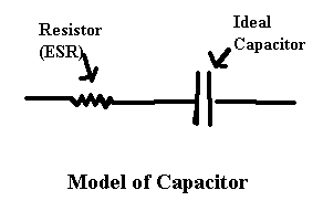
 All capacitors have a certain amount of resistance to the passage of AC current,
this resistance is typically modeled as a resistor in series with a "perfect" capacitor. The value of this
resistor is the ESR. Measuring ESR requires the equivalent of an AC ohmmeter capable of measuring
very low values of resistance, down to about .1 ohms. ESR is frequency dependent.
All capacitors have a certain amount of resistance to the passage of AC current,
this resistance is typically modeled as a resistor in series with a "perfect" capacitor. The value of this
resistor is the ESR. Measuring ESR requires the equivalent of an AC ohmmeter capable of measuring
very low values of resistance, down to about .1 ohms. ESR is frequency dependent.
Electrolytic capacitors have a tendency to increase in ESR over time due to drying out or corrosion.
This increase in ESR has particularly been noted as a problem in switching power supplies. The increase
in ESR increases both voltage drops within the capacitor and the heat produced in the caps due to
resistive heating.
A typical test for ESR involves passing an AC current of around 100 millivolts AC at 100 kilohertz through
the capacitor. The test signal can be sine, square, or pulse waves. The low voltage prevents damage or
interference with associated circuits for in circuit tests. It also limits the reverse voltage applied to
electrolytic caps. At 100 kilohertz, the AC impedance is nearly zero for larger caps.
When measuring caps below 10 uF, the impedance due to the capacitance should be
accounted for.
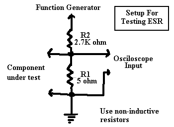
Kits and ready made stand alone testers are available, but tests can also be done using an oscilloscope
and a function generator. The figure to the right is a test setup adapted from the
first reference at the bottom
of the page.
The function generator should be set at 100 kilohertz at perhaps 5 Volts. You will need some reference resistors for comparison, between 1 and 10 ohms (non-inductive).
It's not clear why the author chose 2.7K for R1 as this only puts about 10 mV max. across the test probes. 1000 Ohms would probably be a better choice.
Resistor R1 converts the output of the function generator from a voltage to a current source. The ESR and capacitance of the test part are put in parallel with R2. You could calculate the relationship between the voltage drop across R1and ESR, but for casual use a few reference resistors should be fine. Note that the test only measures AC resistance, a cap with a dead short will show as excellent! In this case the oscilloscope only acts as an AC voltmeter. Originally I thought that using a square wave instead of sine wave would make interpreting the signal more challenging. My own experimentation (See "99 Cent Test Adapter") indicates that using a square wave is actually superior.
A chart of impedance of capacitors and inductors at 100,000 kHz can be found here: HTML Excel 4.0
I was thinking of prototyping some suitable (cheap & simple) signal generators for building a stand alone ESR adapter.
Homebrew Analog ESR Tester
Another Homebrew Analog ESR Tester
"Scope ESR"
(near bottom of page)
Capacitor Testing & Safe Discharging FAQ
http://www.ozemail.com.au/~bobpar/esrmeter.htm
http://www.eds-inc.com/cap.html
http://www.awiz.com/cwinfo.htm
http://www.flippers.com./esrktmtr.html - links near bottom of page
Meter, ESR
http://www.armory.com/~rstevew/Public/TestEquip/CurveTracer.pdf VI Curve Tracer
http://www.ionpool.net/arcade/tech/octopus.pdf Analog Signature Analysis
http://www.techlib.com/electronics/curvetrace.html Curve Tracer
Bare bones ESR tester
Copyright © 2003 by Stephen M. Powell
Comments on this page? E-mail smpowell@taxspam.usa.net
(remove the obvious extra eight character political statement from e-mail address)